.png?mw=640&hash=403c565ab80c4dd45c2d1356634fb74a90428b70)
Among others, the following cross-laminated timber manufacturers are available in the layer structure library:
- Binderholz (USA)
- KLH (USA, CAN)
- Kalesnikoff (USA, CAN)
- Nordic Structures (USA, CAN)
- Mercer Mass Timber
- SmartLam
- Sterling Structural
- Superstructures listed in Lignatec Edition 32 "Cross-Laminated Timber of Swiss Production"
By importing a structure from the layer structure library, all relevant parameters are adopted automatically. The library is continually updated.

- Many predefined components available for easy input of typical connection situations (for example, end plates, cleats, fin plates)
- Universally applicable basic components (plates, welds, bolts, auxiliary planes) for entering complex connection situations
- Graphical display of the connection geometry that is updated in parallel with the input
- The Steel Joints Template included in the Add-on allows you to select from several connection types and, when selected, is applied to your model
- In the Template, there are connections from 3 general categories: Rigid, Pinned, Truss
- Automatic adaptation of the connection geometry, even if the members are subsequently edited, due to the relative relation of the components to each other

Do you know exactly how the form-finding is performed? First, the form-finding process of the load cases with the load case category "Prestress" shifts the initial mesh geometry to an optimally balanced position by means of iterative calculation loops. For this task, the program uses the Updated Reference Strategy (URS) method by Prof. Bletzinger and Prof. Ramm. This technology is characterized by equilibrium shapes that, after the calculation, comply almost exactly with the initially specified form-finding boundary conditions (sag, force, and prestress).
In addition to the pure description of the expected forces or sags on the elements to be formed, the integral approach of the URS also enables a consideration of regular forces. In the overall process, this allows, for example, for a description of the self-weight or a pneumatic pressure by means of corresponding element loads.
All these options give the calculation kernel the potential to calculate anticlastic and synclastic forms that are in an equilibrium of forces for planar or rotationally symmetric geometries. In order to be able to realistically implement both types individually or together in one environment, the calculation provide you with two ways to describe the form-finding force vectors:
- Tension method - description of the form-finding force vectors in space for planar geometries
- Projection method - description of the form-finding force vectors on a projection plane with fixation of the horizontal position for conical geometries

- Selection of nodes in the RFEM model, automatic recognition and assignment of the members connected to the node
- Many predefined components available for easy input of typical connection situations (for example, end plates, cleats, fin plates)
- Universally applicable basic components (plates, welds, auxiliary planes) for entering complex connection situations
- No manual editing of the FE model required by the user, the essential calculation settings can be changed via the configuration settings
- Automatic adaptation of the connection geometry, even if the members are subsequently edited, due to the relative relation of the components to each other
- Parallel to the input, a plausibility check is carried out by the program to quickly detect missing input or collisions, for example
- Graphical display of the connection geometry that is updated in parallel with the input
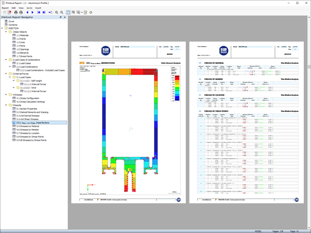
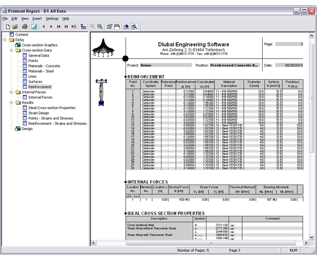
RSECTION also offers everything you need in terms of overview. You can evaluate and visualize all results in an appealing numerical and graphical form. Selection functions support you in the targeted evaluation.
The printout report corresponds to the high standards of the FEA software RFEM and the frame analysis software RSTAB. Any modifications are updated automatically. You don't have to do anything.
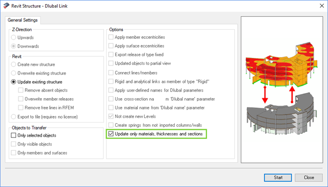
The direct interface with Revit allows you to update the Revit model according to the changes you have made in RFEM or RSTAB. Depending on the modification, the Revit objects may have to be regenerated (deleting the object and subsequent regeneration). The regeneration is performed on the basis of the RFEM/RSTAB model.
If you want to avoid this regeneration, activate the check box 'Update only materials, thicknesses, and sections'. In this case, only the properties of the objects will be adjusted. Changes different from those in material, surface thickness, and section are, however, not considered in this case.
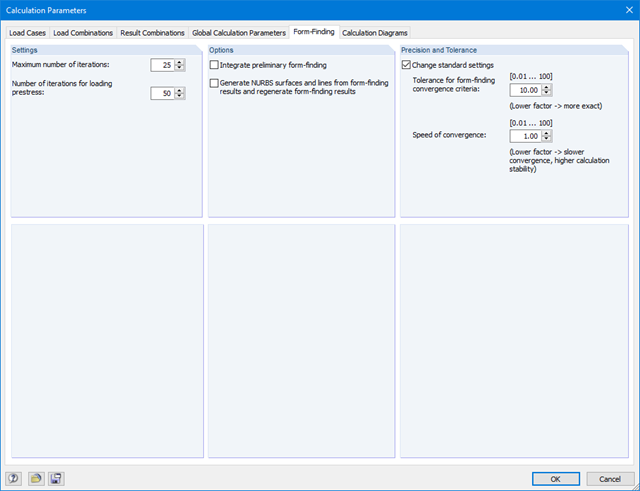
After starting the calculation, the program performs form‑finding on the entire structure. The calculation takes into account the interaction between the form‑finding elements (membranes, cables, and so on) and the supporting structure.
The form-finding process is performed iteratively as a special nonlinear analysis, inspired by URS (Updated Reference Strategy) by Prof. Bletzinger / Prof. Ramm. This way, shapes in equilibrium are obtained considering the pre‑defined prestress.
Furthermore, this method allows you to consider individual loads such as self‑weight or internal pressure for pneumatic structures in the form‑finding process. The prestress for surfaces (for example, membranes) can be defined using two different methods:
- Standard method - prescription of required prestress in a surface
- Projection method - prescription of required prestress in the projection of a surface, stabilization especially for conical shapes
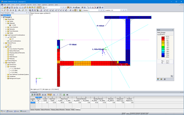
All results can be evaluated and visualized in an appealing numerical and graphical form. Selection functions facilitate the targeted evaluation.
The printout report corresponds to the high standards of RFEM and rstab/rstab-9/what-is-rstab RSTAB. Modifications are updated automatically.
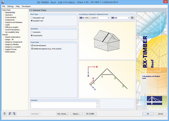
There are various options available for modeling a roof. Graphical representations facilitate the geometry input. Modifications are updated automatically.
In addition, it is possible to consider cross‑section weakening on supports. Optionally, you can define if the design of support pressure on the rafter side should be performed.
Permanent loads (for example, roof structure) can be entered using the comprehensive and extensible material library. Loads due to cantilevers and collars/ties can be entered separately. Generators integrated in RX-TIMBER Purlin allow for convenient generation of various wind and snow load cases. You can manually add any concentrated and distributed loads.
Load cases are displayed graphically and superimposed in automatically generated load combinations according to EC 5. For stability and serviceability limit state designs, you can change the data manually, for example, for example, for cantilevers (roof overhang), it is necessary to ignore the SLS.
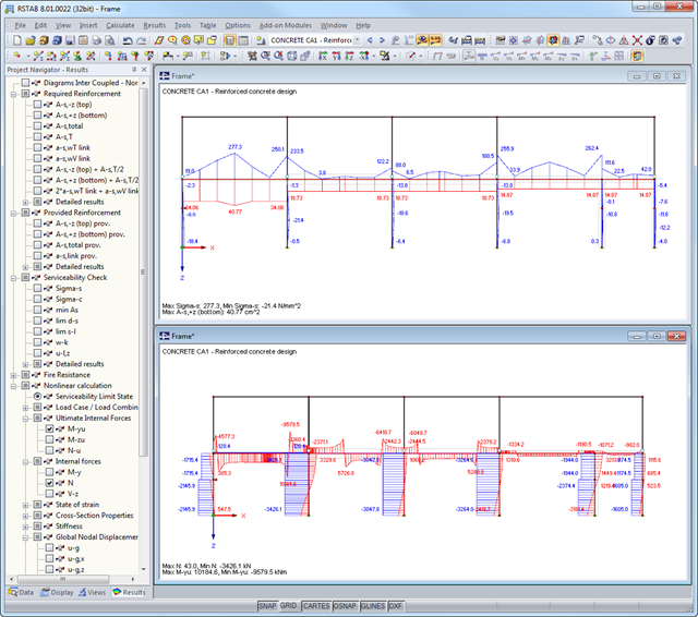
After the calculation, the module shows clearly arranged tables listing the required reinforcement and the results of the serviceability limit state design. All intermediate values are included in a comprehensible manner. In addition to the tables, current stresses and strains in a cross‑section are represented graphically.
The reinforcement proposals of the longitudinal and the shear reinforcement, including sketches, are documented in accordance with current practice. It is possible to edit the reinforcement proposal and to adjust, for example, the number of members and the anchorage. The modifications will be updated automatically.
A concrete cross‑section, including reinforcement, can be visualized in a 3D rendering. This way, the program provides an optimal documentation option to create reinforcement drawings, including steel schedule.
Crack width analyzes are performed using the selected reinforcement of internal forces in the serviceability limit state. The result output covers steel stresses, the minimum reinforcement, limit diameters, and the maximum bar spacing, as well as crack spacing and the maximum crack widths.
As a result of the nonlinear calculation, there are the ultimate limit states of the cross‑section with defined reinforcement (determined linear elastically) as well as effective deflections of the member considering stiffness in cracked state.
Results are displayed in result tables sorted by required designs. Clear arrangement of the results allows for easy orientation and evaluation.
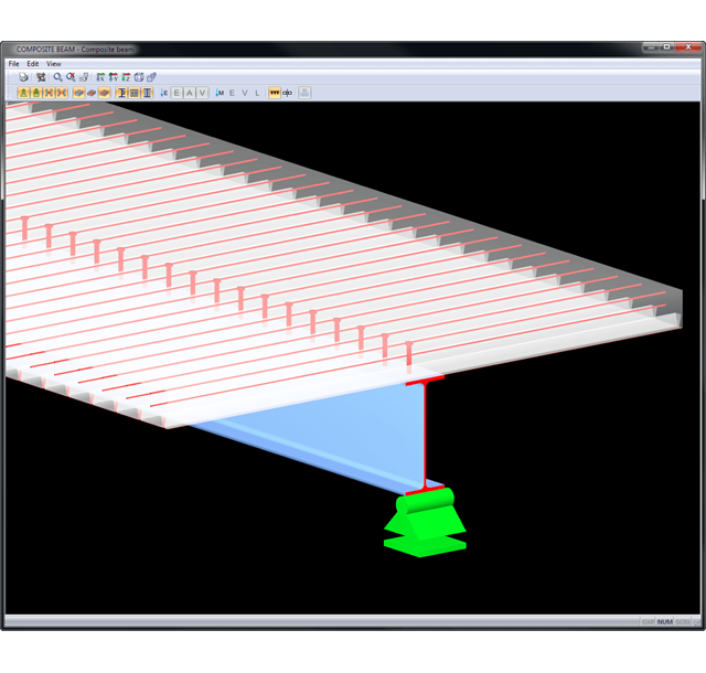
Ultimate Limit State Design:
- Bending and shear force resistance with interaction
- Partial shear connecting of ductile and non-ductile connecting elements
- Determination of required shear connectors and their distribution
- Design of longitudinal shear force resistance
- Design of connection with shear connectors and of connector perimeter
- Results of governing support reactions for construction and composite stage, including loads of construction supports
- Lateral-torsional buckling analysis (for continuous beams and cantilevered girders)
- Check of cross-section classes as well as of plastic and elastic cross-section properties
Serviceability limit state design:
- Deflection Analysis
- Deformations and initial pre-cambering determined with ideal cross-section properties from creep and shrinkage
- Analysis of natural frequencies
- Crack width analysis
- Determination of support forces
All data are documented in a clearly arranged printout report, including graphics. In case of any modification, the printout report is updated automatically. COMPOSITE-BEAM is a stand-alone program and does not require the RSTAB license.

- Design of knee joints, T-joints, cross joints, and continuous column connections with I-shaped sections
- Import of geometry and load data from RFEM/RSTAB or manual specification of the connection (for example, for recalculation without an existing RFEM/RSTAB model)
- Flush top connections or connections with bolt row in extension
- Design of positive and negative frame joint moments
- Various inclinations of right and left horizontal beams as well as application to frames of duopitch and monopitch roofs
- Consideration of additional flanges in a horizontal beam, for example for tapered sections
- Symmetrical and asymmetrical T-joints or cross joints
- Two-sided connection with different cross-section depth on the right and left
- Automatic preliminary design of bolt layout and required stiffening
- Optional design mode with possibility to specify all bolt spacing, welds, and sheet thicknesses
- Screwability check with adjustable dimensions of used wrenches
- Connection classification by stiffness and calculation of the spring stiffness of connections considered in the internal forces determination
- Check up to 45 individual designs (components) of the connection
- Automatic determination of governing internal forces for each individual design
- Controllable connection graphics in rendering mode with specifications of material, sheet thickness, welds, bolt spacing, and all dimensions for construction
- Integrated and flexibly extensible settings of National Annexes according to EN 1993-1-8 standard
- Automatic conversion of internal forces from structural analysis into respective sections, also for eccentric member connections
- Automatic determination of initial stiffness Sj,ini of the connection
- Detailed plausibility check of all dimensions, including specifications of input limits (for example, for edge distances and hole spacing)
- Optional application of compression forces to a column through contact
- Possibility to update the cross-section depth of horizontal beams in case of tapered connections after connection geometry optimization in RF-/FRAME-JOINT Pro
All results can be evaluated and visualized in an appealing numerical and graphical form. Selection functions facilitate the targeted evaluation.
The printout report corresponds to the high standards of RFEM and -rstab RSTAB. Modifications are updated automatically. Furthermore, you can print the reduced report in a short form, including all relevant data and a user-defined cross-section graphic.
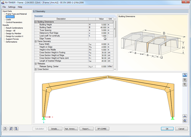
There are various options available for frame modeling. Graphical representations facilitate the geometry input. Modifications are updated automatically. Basic dimensions as well as geometrical data are entered in tables. During the input, the program checks the conditions required for the beam creation (for example, lamellas forming a curve) according to the defined standard. The most important geometry parameters are updated and displayed.
The relevant timber grade of the material can be selected from the material library. All material grades for glulam, hardwood, poplar and softwood timber specified in EN 1995-1-1 are available. Furthermore, it is possible to generate a strength class with user-defined material properties in order to extend the library. Permanent loads (for example, roof structure) can also be entered using the comprehensive and extensible material library.
Generators integrated in RX-TIMBER Purlin allow for convenient generation of various wind and snow load cases. By clicking the information buttons, the map of wind and snow zones for the relevant country is displayed. The corresponding zone can be selected with a double-click. Load cases can be checked graphically. However, you can enter load specifications manually as well. According to the generated loads, the program automatically creates combinations for the ultimate and serviceability limit states as well as for fire resistance design in the background. The generated combinations can be considered or adjusted by user-defined specifications.
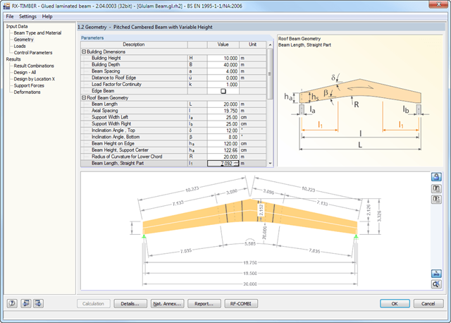
There are various options available for beam modeling. Graphical representations facilitate the geometry input. Modifications are updated automatically. Deflection of cantilevers can be set in the serviceability limit state design, independently of the deflection in the span.
In order to enter permanent loads (for example, roof structure), you can use a comprehensive and extensible material library. Generators integrated in RX-TIMBER Purlin allow for convenient generation of various wind and snow load cases.
Load cases are displayed graphically and superimposed in automatically generated load combinations according to EC 5. This way, the required input data are reduced to a minimum. However, you can enter load specifications manually as well.
There are various options available for beam modeling. Graphical representations facilitate the geometry input. Modifications are updated automatically. Deflection of cantilevers can be set in the serviceability limit state design, independently of the deflection in the span.
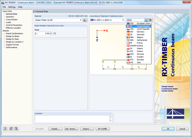
The relevant timber grade of the material can be selected from the material library. All material grades specified in EN 1995-1-1: 2004 (EC 5) or DIN 1052:2008-12 and the selected National Annex are available for glulam, hardwood, and softwood timber. Furthermore, it is possible to generate a strength class with user-defined material properties in order to extend the library. Permanent loads (for example, roof structure) can also be entered using the comprehensive and extensible material library.
Generators integrated in RX-TIMBER Purlin allow for convenient generation of various wind and snow load cases. Load cases are displayed graphically and superimposed in automatically generated load combinations according to EN 1990, DIN 1055-100, or DIN 1052. This way, the required input data are reduced to a minimum. However, you can enter load specifications manually as well.
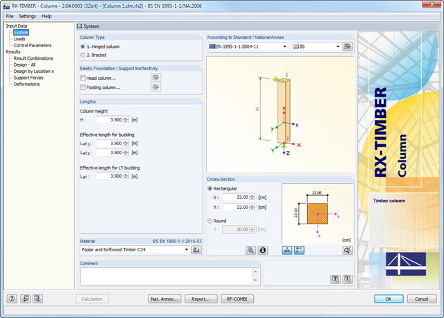
There are various options available for column modeling. Graphical representations facilitate the geometry input. Modifications are updated automatically. The relevant timber grade of the material can be selected from the material library. The strength classes of glulam, poplar, and softwood timber are available as defined in the respective standards.
Furthermore, it is possible to generate a strength class with user-defined material properties in order to extend the library. The load cases entered can be checked graphically and combined automatically in load combinations.
After the calculation, the module shows clearly arranged tables listing the required reinforcement and the results of the serviceability limit state design. All intermediate values are included in a comprehensible manner.
The results of RF‑CONCRETE Members are displayed as result diagrams of each member. The reinforcement proposals of the longitudinal and the shear reinforcement, including sketches, are documented in accordance with current practice. It is possible to edit the reinforcement proposal and to adjust, for example, the number of members and the anchorage. The modifications will be updated automatically. A concrete cross‑section, including reinforcement, can be visualized in a 3D rendering. This way, the program provides an optimal documentation option to create reinforcement drawings, including steel schedule.
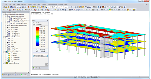
The results of RF-CONCRETE Surfaces can be displayed graphically as isolines, isosurfaces, or numeric values. It is possible to sort the longitudinal reinforcement display by required reinforcement, required additional reinforcement, provided basic or additional reinforcement, and provided total reinforcement. The isolines of the longitudinal reinforcement can be exported as a DXF file for further use in CAD programs as a basis for reinforcement drawings.
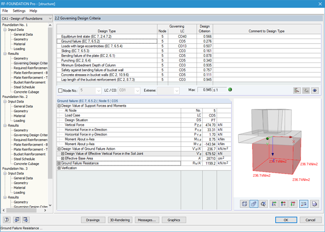
It is possible to perform the following designs:
- Equilibrium limit state design
- Uplift limit state design
- Ground failure (soil contact pressure) design
- Strong eccentric loads design
- Design of foundation torsion and limitation of gaping joint
- Sliding design
- Settlement calculation
- Bending failure design of the plate and bucket
- Punching shear design
Foundation and bucket dimensions can be user-defined or determined by the module. You can edit the determined reinforcement manually. In this case, the designs are updated automatically.